Monday, June 26, 2023

Battle of Scarif - creating the base of the citadel tower


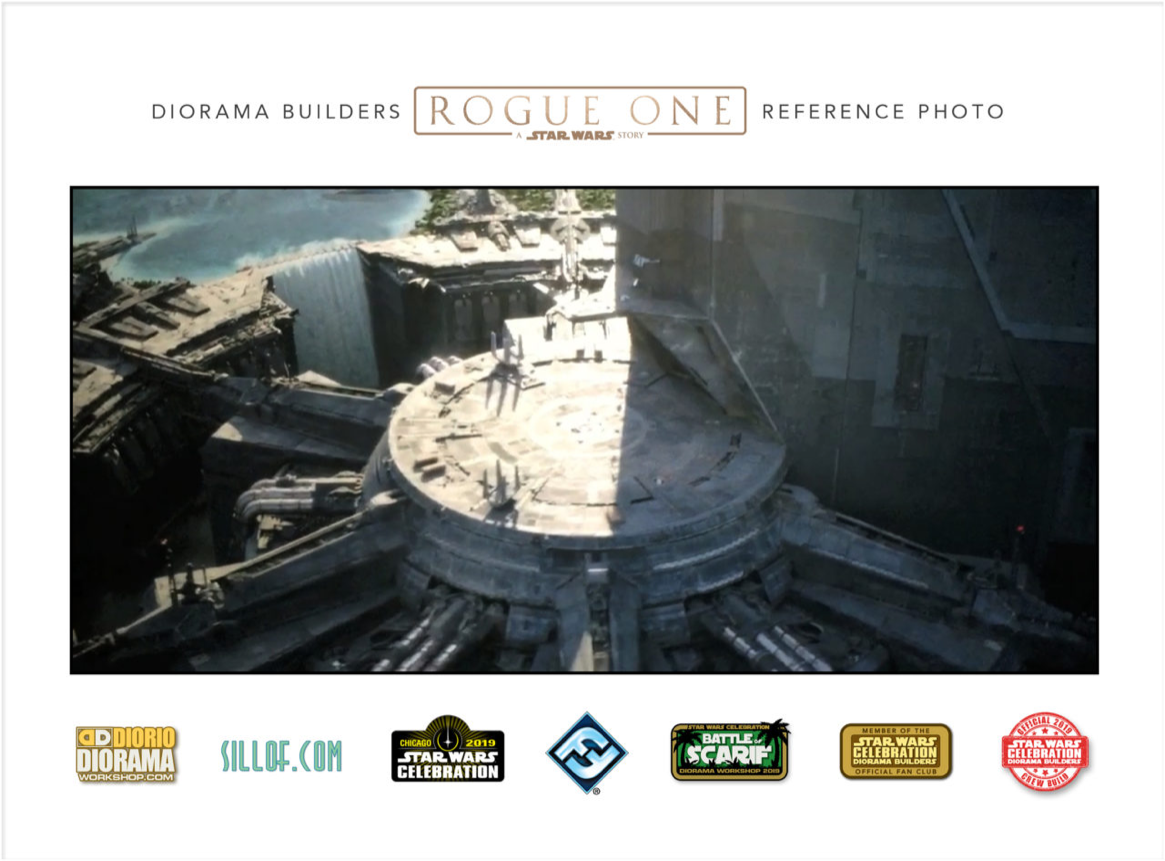
In my last post I looked at the process I went through cutting out and creating the elements of the base and starting to turn it from bare foam into something that looks like a Star Wars base. Initially this required looking very closely at a range of reference photos and straining to make out obscure parts of the infrastructure. I can’t stress enough how important this step is if you want your model to match your reference. It’s at this stage that I begin to determine the height, depth and angle of things and as well as establishing my colour range and palette. It’s also really annoying when you find a photograph later in the build that shows an element in a different light so I find it’s very worthwhile spending time on your research followed by careful organisation of the results so that you can find things. But also, once you’ve made your decision, go for it and don’t worry about it afterwards.


Central base

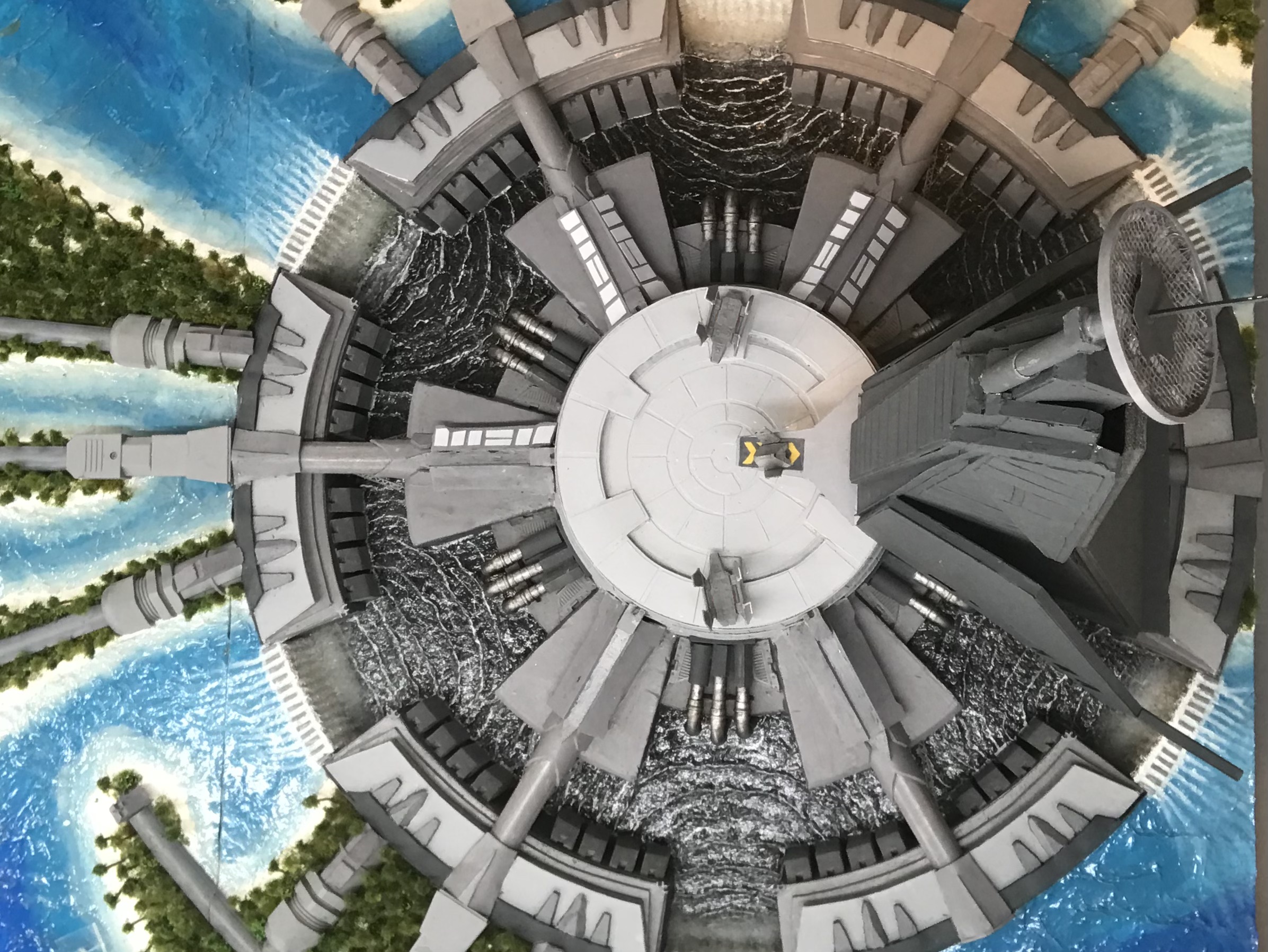
This was the first time I’ve used pink XPS insulation board so before I worked the surface I applied a quick and thin application of polyfilla. I’m not sure it was needed but I got into the habit and it didn’t take very long. I then bevelled the edge of the central spikes facing the reservoir.


For the central landing pad I needed the sides to slope inwards and so remarked the top of the pad by knocking 3mm off the radius and then cut the sides slowly and carefully using the snap off knife. I was able to sand it and was pretty happy with the result even though it was mostly judged by eye. To make the landing pad look like the images from the movie I used 3 layers of 2mm deep EVA foam. This allowed me to create water drainage channels around the edge of the centre, raise the edge and create ramps down to central pad.


I then marked out and cut plasticard in concentric geometric patterns and glued it onto the model. I Dremelled the edge and glued on a plasticard strip to give an even and uniform edge. Gaps and errors were filled.


The side was covered with more plasticard trapezoids and a U shape styrene strip to provide some variation.

Buttresses

I started with the outer ring of the reservoir and the buttresses. The photos suggested that there were 8 buttresses on the outer ring on the projection between each weir. It also looked like there was a gap in the middle. Measuring the length of wall and putting in a break and a gap between each buttress gave me the width of each buttress. I gauged their height as well. Here I was doing this visually as my reservoir is not as deep as the one in the movie simply for practical reasons. In order to try and uniformly place the buttresses I cut a spacing template.


Each buttress was cut from 10mm deep pink xps insulation. I used the snap off knife to cut the angled top. This is where I should really have used a hot wire cutting table. Although I tried you just cannot get consistency cutting by hand even with everything measured and marked out. 


Then to break up the uniformity I cut a notch in the middle at the top. Then I rubbed in some filler and sanded them down. I used dressmaker pins to hold them in place whilst I waited for the glue to dry.

Transit Lines

The six transit lines were quite complicated. There is a height variance between the edge and the central base, there’s a a spur projecting from the centre and a complex range of overlapping layers as the line expands.


I used D-line 20mm by 16mm D shaped electrical ducting for each of these central transit lines. This was pretty straightforward as I could just roughly cut them to length.


The central spurs began with a shaped trapezoid section of 10mm XPS. I used another block to get the elevation I wanted for the line. I then cut pieces of the 2mm EVA foam to act as sides with a piece of plasticard covering the centre. One of the last things I did on the build was add plasticard shapes to break up this central roofing area.

I also added some 2mm cork onto the ducting by the spur to break up the transition into the spur housing. Underneath the transit line I added a 5mm styrene tube and some styrene gantries as these can be seen in the reference photos.

Cooling water inflow pipes

I spent a lot of time looking at my options. I looked at all kinds of piping and pipe systems including air filtration systems, garden irrigation systems, food piping to try and find a system I liked and was within a reasonable price range. And I just couldn’t find a system that met my requirements. However the solution turned out to be fairly simple.

I purchased some 8mm diameter styrene tubing from evergreen and some 8mm copper right angle pipe joints that are used I think with boiler pipes. They fitted together beautifully. The only issue is that the right angle joints aren’t quite right but I’m probably the only person who will notice.

I also wanted to ensure that the pipe joints, visible in the photos, could be seen on the model. To do this I scored horizontal lines every 5mm into the styrene, that way the later inkwash would colour it before I dry brushed it.


I then used some railway cutting edges as the background for the ducts entering the base. I used some hexagonal and square pipes to match the photos and cut some old plastic model pieces for background. One of the things I’m really pleased about is that I inherited my father’s left over railway modelling materials and I have been able to incorporate some of them into this model. I think he would have liked that.


Outer Ring

I took a fairly straightforward approach to the outer ring. It looks fairly complex in the photos but I just simplified it and built it up in layers of 3mm foam board. These were cut in arcs using the compass and the laid out. Each piece varied in width as the edge seems to slope inwards. I used more of the styrene gantry to provide depth and to elevate the top piece so that it slopes inwards.


The edge was covered with EVA foam and other bits with filled with flexible filler. On top detailing was provided by the 2mm cork as I found this much easier to work with when the pieces were so small. Again filler was used to smoothen things out and a piece of EVA foam was cut to fit over them.


Paint scheme

I visited my local DIY store and picked up a selection of paint taster pots in various shades of grey, from very light through to black. I used these to paint the various elements generally working from the outside and bottom with the darker greys towards the centre and top with the lighter greys.

Lessons learnt

So this was my first time working with foam and my main take away is that I really should have bought a proper hot wire cutter with adjustable angle cutting arm. This would have made my life much easier and would have resulted in a more accurate and consistent build.

Doing everything 6 times, or in some cases 12 or 18 times got really old, really quickly. It added considerably to the time taken to recreate this model.

Foam, in multiple different forms, is really easy to work with. You just need to choose the right kind of foam for the job. It’s fairly easy to hide errors with filler or some other covering. It cuts easily, glues well, can filled, smoothed and painted. I’ll definitely be looking to use it again on future projects.

So that’s it for the build of the tower base. Next time I’ll talk about creating the islands and the various solutions I used to create the water on the model. Till then keep your dice rolling.


Charles the Modeller 


Sunday, June 18, 2023

Battle of Scarif - cutting the base of the citadel tower


In my previous posts I've talked about the initial design and then the creation of the boards themselves. This post will look at the creation of the base of the tower. Again, my starting point was the map. 

Having neatly split my map in a 4 by 6 grid I was able to adjust the positioning to get the tower base to fit neatly into a 60cm by 60cm area at the bottom right hand side. This was crucial as will become clear later. What was also clear was that it was a complex geometric design. When checked against reference photos it was also clear that there were multiple different height levels as well, above and below the base layer of the boards.

The next step was to create a reference template of the various concentric rings and angles. This required serious thought and repeated measurements from the map and reference photos. This had to be correct as the visual appeal of the full table would be determined from these measurements. I fired up MS Word and played around with the shapes at a quarter size. As a starting point I decided that each ring would be 5cm deep but with the central landing pad having a radius of 10cm.


I think at this point it's worth noting that the movie's design and production team based their design on the Imperial symbol. It's a clever Easter Egg that isn't visually obvious but is pretty cool.


I couldn't make the tower base any bigger than the 60cm diameter because I needed to cut out a whole ring of the board to create the cooling reservoir. If I exceeded that size limit I might reach the edge of my board and I couldn't cut through or into the board edge. Once the ring measurements were decided the angles could be measured and drawn onto the plan. I simply printed the page and got out my pencil and protractor. 

Where there were 6 spurs meant dividing 360° by 12, for 30° angles, one sticking out, and one not alternating around the base.

The 6 weirs, whilst geometrically spaced, were clearly smaller than the structure between them and a rough measure suggested they were about 15°. This seemed logical and visually pleasing so that's what I went with. I had to be careful with positioning as the weirs were the outermost point of the tower base. The easternmost weir was at the 3 o’clock position and so the tower centre was moved just over 2 cms to the left to ensure I didn’t hit or cut into the board’s wooden edge.

With an outer ring with a 30cm radius I had to order a large compass specifically for this build. I tried the string round a pin but it just didn’t work. I pencilled in each of the rings and then used a protractor to mark all the various angles needed to outline the basic design onto the board. 

The next step was to cut it all out. I used a large snap off knife with the blade extended to cut the initial shape into the foam. This seemed to work pretty well. I was able to lever out the central section where the cooling reservoir was and only had to make some minor tidying up cuts to the edges where I wasn’t completely happy that the sides were vertical. For my first attempt at cutting foam to a specific shape though I was very pleased with the result. As I was soon to discover though having a hot wire cutter, specifically one on a machine with an adjustable angle arm would have been a god send with this build. I definitely regret not getting one, but hey ho, it’s now on the Christmas list!

I then raised the middle section slightly, by 10mm, using pink xps board. This was set in slightly so I could bevel the edge. The inner most circle got another xps board layer and then a disc of 25mm cetoflex added on top to create the base for the central landing pad.


This was all glued down and gave me the basis for creating all of the tower base detailing which is what I will cover in the next post.

Keep those dice rolling!


Charles the Modeller 


Friday, June 2, 2023

Battle of Scarif - Building the base boards


Having decided to build an 1800mm by 1200mm board to refight the battle of Scarif, and having found a map that I liked, I now needed to build the boards themselves. This wasn’t as straightforward as I would have liked. I know from experience that I can fit three 1200mm by 600mm boards into the stacking system I’ve built for my car, so I knew how big each board was going to be. The challenge came from the depth each board would need to be.

I googled other Scarif games that people have put on, including some enormous 28mm games and also looked at other models of Scarif that people have built including some impressive Lego versions. Whilst all of them were great in their own ways none of them seemed to have really recreated the whole battlefield in detail, with most in particular, just building the tower itself and at best paying lip service to recreating the tower base. Quite understandable, but this gave me the chance to do something unusual.

The base of the tower is very complex. It’s very geometric, in concentric patterns replicated 6 times. There are multiple transit lines intersecting with the outer ring, 6 main arteries connecting with the tower centre, ducts, gangways, 6 massive weirs with attendant waterfalls and enormous pool as well as a landing pad, all of which are on multiple different height levels. The rest of the board is fairly straightforward with low island atolls and sea - a pleasant change after the contours of my Imjin board!

Luke Fellows, of Geek Gaming Scenics, builds his boards using 6mm MDF or ply with 20mm or 25mm battens round the edges with the middle infilled with polystyrene insulation. I’ve built my last few boards the same way and I really like the system. If you are not familiar, check out this video he did here as it’s a very effective system.


I still wanted to use this system but the problem was with the six waterfalls surrounding the tower. I wanted to represent these and they needed to seem massive. A 25mm drop was not going to be sufficient to convey the scale of the complex. I thought that if I doubled that drop to 50mm I could probably make that work. That would allow me to infill the board with 50mm insulation and keep to the same system just with deeper insulation. 

The problem was that I couldn’t find any wood cut neatly, with clean edges and smooth that was exactly 50mm. Everybody that showed up in the search results for 50mm battens, strips or whatever actually provided the cut at about 44mm. There was clearly some major discussion and agreement amongst British wood suppliers that nobody needed exactly 2 inch thick wood and that 1inch and 3 quarters was just fine. Except it wasn’t for me. It would have meant slicing the top 6mm of whatever insulation I needed across the face of the insulation boards! Not going to happen!

Going any deeper than 50mm, up to say 75mm or 100mm, which I could get wood for was going to cause significant weight issues as well as imperilling my stacking system. So I was stuck at 50mm. The only option was to cut wider wood down to 50mm. I picked up some 119mm wide by 18mm thick smooth finished timber and fired up my rarely used table saw. With some test cuts and the odd error I was able to cut the timber lengthways into 50mm strips. 

These were then cut into the appropriate lengths using a mitre saw, which is when I realised I hadn’t cut enough and had to go back and buy more timber. Basic maths fail and an extra day’s effort required. D’oh!

I glued and screwed the wooden strips to some 6mm MDF boards that I checked were all absolutely the same size. I used clamps and corner angles to ensure that the sides were perfectly square and absolutely vertical and screwed them into each other at the corners. Whilst narrower than I’m used to using at 18mm thick I believe the height at 50mm will prevent any warpage.

I then cut Reticel 50mm thick insulation board to fit into the middle of each board and glued it in place using spots of gorilla glue.

I overlaid the top with some good quality wall lining paper carefully laid edge to edge and glued down at the edge of each board to minimise potential for warping.

I filled in gaps and screw holes with wood filler, sanded everything smooth and applied two coats of black gloss paint. I now had a blank canvas upon which to create my model.

Next time I will look at how I created the shape and design of the tower base. Until then keep the dice rolling!


Charles the Modeller 


Battle of Scarif - adding all the bushes and trees

In previous posts I’ve covered the building of the boards, the seas, the islands and the transit systems for my battle of Scarif board. In t...